System overview
![]()
Most people understand
why a stereo system with a center channel and a surround channel can produce
more interesting audio effects than a system with just the left and right
channels alone. Unfortunately, audio media has traditionally been recorded with
only two channels, meaning that there simply isn't a convenient place to stick
the center and surround channel information on a typical videocassette. This is
where center and surround channel encoding comes into play. The encoding
process stores the center and surround channel information along with the left
and right channel information, effectively squashing 4 signals (left, right,
center, and surround) into 2 signals (left and right). Eventually, the decoder
extracts the left, right, center and surround channels from these two encoded
signals.
Encoding the Surround
and Center Channels
Even though the encoding
mechanism is not a part of consumer electronics (encoding is performed at the
recording studio), a brief discussion of the process is included in our report
because the decoding circuitry is dependent on it.
Figure 1 illustrates how
the center and surround channels are encoded into the left and right channels
to produce the "Lt" and "Rt" outputs. Encoding the center
first involves a 3 decibel signal reduction, effectively halving its magnitude.
This halved center signal is then added to both the left and right signals. Encoding
the surround channel also starts with a 3 decibel reduction in signal
amplitude. The reduced surround signal then passes through a band pass filter,
eliminating high and low frequencies. Presumably, this filtering makes the
decoding process easier on hardware that has limited bandwidth, as it serves
little other functionality. After being shifted 90 degrees in positive and
negative directions, this filtered surround signal is then added to the left
and right signals, respectively.
This may seem like a
bunch of random signal arithmetic, but there are three important effects of
this encoding mechanism that should be mentioned. First, the center channel
information encoded in the left signal is in phase with the center channel
information encoded in the right channel. Second, the surround channel
information encoded in the left signal is exactly 180 degrees out of phase with
the surround channel information encoded in the right channel. Third, the
center and surround signals are only added to the left and right signals at
half volume, meaning that the left and right channels still sound pretty close
to what they did before the encoding process. These observations play an
important role in the decoding mechanism, as described in the following
section.
Decoding the Surround
and Center Channels
After understanding how
the encoding scheme works, we designed a simple method of decoding the left, right,
center, and surround channels from the encoded left and right channels. Our
method takes advantage of the general properties of the encoding process,
without implementing some of the more complicated (and more expensive)
operations of commercial decoders.
As Figure 1 illustrates,
our "decoded" left and right signals are obtained by simply passing
through the encoded left and right signals. In other words, there is really no
decoding taking place at all! Recall that the center and surround channel information
is added onto the left and right signals at half amplitude. Sound coming from
the left and right speakers actually contains the center and surround channel
information as well, but this is not necessarily a bad thing. What the listener
can hear of the center and surround information will effectively create a
subtle blending effect between adjacent channels.
To recover the encoded
center information, the decoder performs a summing operation between the left
and right input signals. Signals that are in phase on both input channels are
added, effectively doubling the amplitude of this in phase information. Because
of the -3db reduction in amplitude during the encode process, the center output
from the decoder will be restored to the 0db reference level. Out of phase
information is summed to equal zero by this information, meaning that the out
of phase surround information is not present at all in the center channel. An
artifact of this process is that some left and right channel information is
added to the center channel, but is down 3db in magnitude. See Figure 2 for an illustration of how the center signal appears
originally, encoded onto the Lt and Rt tracks, and after decoding. Note the
waveform has additive noise as a result of decoding. This noise is actually
sound originally recorded as left or right channel information.
To obtain the encoded
surround information, the decoder performs a difference operation, subtracting
the right input signal from the left input signal. This effectively adds
signals that are exactly 180 degrees out of phase, precisely the phase
difference of the encoded surround information. Again, the amplitude of this
out of phase information is doubled, and the surround output from the decoder
will be restored to the 0db reference level. The in phase center channel
information will be subtracted to equal zero. Again, some left and right
channel information is present in the surround center channel, but at half
magnitude. Figure 3 illustrates the
conversion of the original surround signal to the encoded signal and the
decoded result.
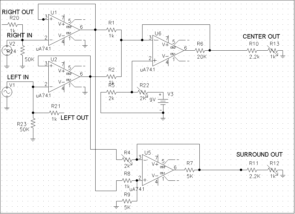
Figure 4 shows the schematic of our circuit.
The upper right op-amp performs the summing operation and the lower right
op-amp performs the difference operation. The four op-amps on the left are simply
voltage followers used to buffer the inputs to the sum and difference op-amps. Each
of these buffers contains a 10 Ohm resistor used to offset the input voltage. This
prevents a clipping effect on the buffers' outputs. For the difference op-amp,
this offset is naturally eliminated when the two signals are subtracted. For
the summer, the offsets will be added to each other, resulting in an higher
input voltage for the summing op-amp. This effect is alleviated by the
potentiometer connected to the positive terminal of the summing op-amp; it
controls an offset voltage that compensates for this higher input voltage. The
potentiometer on the input of the difference op-amp controls the relative
balance between the left and right input signals. By tweaking the input
resistance of this input, we could match its input signal very closely with the
other signal and minimize any noise at the output of the difference op-amp. The
remaining two potentiometers control the volume of the summing signal and
differentiated signal, respectively.
Dolby Surround and Dolby
Pro-Logic
Our testing also
involved examining the Dolby Surround and Dolby Pro-Logic decoders. The model
used was the Pioneer VSX-502 which is an integrated amplifier/decoder. We were
unable to examine the specific circuit schematic of the Dolby decoder because a
single IC was used to perform decoding. We could, however, examine the block
diagrams of the Dolby decoding processes to determine how the Dolby circuit
likely differs.
Dolby Surround is a
three channel surround decoder that ouputs a left, right and surround channel. The
surround channel undergoes a delay and is lowpass filtered before playback.
Dolby Pro-Logic is the
modified form of Dolby Surround decoding that adds a center channel. Pro-Logic
also adds a steering logic to "guess" which channel sounds should be
coming from and cancel the signal at all other speakers besides that channel or
to move into 'passive' operation when no dominant signal is detected. The
surround channel is also filtered and delayed as in the Dolby Surround system. Dolby
claims this logic results in greater channel separation over the 3db
theoretical limit.
Both Dolby decoding
technologies can be implemented in either analog or digital ICs. These ICs were
found to range in price from under $100 up to $800 for versions that
incorporated multiple surround decoding algorithms.