How to set
the DPA 220
аSet the R13 toа
theа middleа positionа
andа theа R23а
toа minimum
аresistance. Connect aа signalа
generatorа toа theа
inputа andа an
аoscilloscope to the output. Take out a
fussа inа
oneа brancheа of
power supply
and connect a current meter instead. Slowly raise the
аsupply voltage above zero and watch the
current. Since aboutа +/-
а3а
Vа theа ampа
shouldа startа toа
workа andа thereа
shouldааа be
symmetrically
limited signal at the output. Ifа
theа current аdoes
not grow
too high (30 mA), raise the voltage to the full +/- 40а V
and raise
the input signal to check the symmetry of limitation.
аIf everything's all right, connect
4/8ohms/100Wа loadа andа
raise
the
signalа levelа toа
3а dBа underа
limitation.а Whenа theа
power
transistors
grow hot (5 minutes?) set the signal generatorа
toа 20
kHz at the
output voltage of the amp 1V. Aа
distortionа shouldа be
visible on
the sinusoid - eliminate it by raising the BIAS current
by R28. A
correctly set amp should have a BIAS current about 50 mA
in each
branch of power supply.
аThen connect a DC voltage meter to the output
and by R13 setа as
small DC
output voltage as possible. 10 mV is acceptable, 1 mVа is
possible
with a bit of patience. You can check frequencyа
response
if you
want. In the end you can check the current securing circuit:
аShorten the output with a 0.1 ohm resistor Set
theа inputа signal
to 1
kHz/500mV. Slowly raise the supplyа
voltageа -а thereа
should
appear a
sharply limited signal on the output with smallа
glitches
on the
front edges. If the circuit works as described, you can try
complete
short circuitа atа theа
nominalа voltageа -а
theа current
consumption
should be about 3A in each branch of the supply.
My own
advice: when you start and set the amp for the first time -
or any
otherа circuitа -а
beа absolutelyа careful.а
Whenа changing
configuration
of signal generator, oscilloscope, meters andа
load,
ALWAYS
switch off the power supply. I even unplug it ever sinceа i
burned a
TDA2040. Another practiceа hasа provenа
usefulа overа the
years: for
the first power-up, replace fuses in both powerа
supply
rails with
lightbulbs - I'm using regular 100W / 240V bulbs.
аNaturally you mustn't apply load toа theа
amp'sа outputа in аthis
setup. If
something goes wrong, the lightbulbs start toа
glowа and
basically
limitа theа currentа
flowingа throughа theа
circuit.а If
everything's
right, the lightbulbs remain cool and the amp behaves
as
expected.
аThen you can try to make them glow byа turningа
theа bias-current
trimpot. If
you succed, you know you have another clueа
everything
is working
fine. Then you turn the bias current back to zero,а put
the
fusesа backа andа
youа canа proceedа
withа theа aforementioned
procedure.
In general, it cost me about a handfulа
ofа transistors
to gain
this knowledge. Note that the frequency response is a full
graph and
measured 1 dB under limitation (=maximum sinus power)а -
when
measuring voltage, value in decibels = 20 log (amplification)
- 6 dB
means amplification 2x.
The DPA 220
schematic
The DPA 220
low detail schematic (click on the imageа
toа seeа the
high
detailed version (47 Kb)
Do not try
to print this picture in Netscape because it's too big.
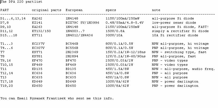
T1 to T6
create the input differential stage. The D7 and D8а zener
diodes
stabilize at 5V. Theseа areа justа
theа simplestа low-power
zeners,а onlyа
theyа haveа toа beа coupledа
inа toleranceа ofа 200
milivolts,
which should not be a problem.а T1а toа
T6а areа common
allpurpose
low-power transistors withа highа Hfe.а
Theseа sixа and
maybe the
next four have to be coupled in tolerance of 25%.
The T7 and
T8 are fast, switching application types.
T9 and T10
have to be fast and must hold a high voltage, thusа the
best are
the "video" types - BF469/470. T15 and T16 areа theа same
types.
The C9, C10
and C15 should stand voltages higher than usual 50 V -
I don't
know why.
D3 to D6
can be any silicon type, notа
Scottky,а theа onesа
listed
below are
just allpurpose low-current ones for 150 V. These diodes
should be
rather fast - "switching types".
The T11 and
T12 stabilize the BIAS current forа
theа powerа stage.
T11 also
serves as a temperature sensor, andа
isа mountedа toа the
cooler of
power transistors.
T13 and T14
secure the output current - in cooperation with R38 and R39.
The output
transistors used here are Teslaа
typesа -а Teslaа
isа a
former
local devices manufacturer - the pair in each branch can be
replaced
with a single power darlington,а
likeа BD649/BD650.а They
should have
Pc > 150W, Ic > 15A, Uceo > 100V.
In this
case obviously the R38+R40 /а
R39+R41а mustа beа
connected
parallel.
These resistors should be able to absorb high power - at
least 2 W,
but I'd use 5W ones.
The output
filter improves stability of the amp when workingа with
complex
impedanceа of аspeakersа
-а itа isа
quiteа important.а The
resistors
are high-power ones again, the coil is 13 turns of a 1.2
mm wire on
a 8 mm thorn (diameter). R43 is placed coaxially in the
coil.
The
schematic also includes power supply capacitors andа rectifier
- the
capacitors' size is not crucial, generallyа
theа biggerа the
better. The
rectifier originallyа consistsа ofа
fourа siliconа 10A
diodes, but
you can use whatever you have - rectifier bridgeа etc.
The trafo
should be a 2 * 30 V / 7 A type so that you have +/-а 40
V on the
power supply capacitors.
In the
scheme there's also a thermistor thatа
isа supposedа toа be
connected
to some additional circuits that secure temperatureа and
other
things.
The
complementary input stage of DPA amps is an unmistakableа heir
of earlier
designs published by Mr. Borbely in severalа
issuesа of
Volume 1984
of the Audio Amateur.
How to set
the DPA 220
аSet the R13 toа
theа middleа positionа
andа theа R23а
toа minimum
аresistance. Connect aа signalа
generatorа toа theа
inputа andа an
аoscilloscope to the output. Take out a
fussа inа
oneа brancheа of
power
supply and connect a current meter instead. Slowly raise the
аsupply voltage above zero and watch the
current. Since aboutа +/-
а3а
Vа theа ampа
shouldа startа toа
workа andа thereа
shouldааа be
symmetrically
limited signal at the output. Ifа
theа currentа does
not grow
too high (30 mA), raise the voltage to the full +/- 40а V
and raise
the input signal to check the symmetry of limitation.
аIf everything's all right, connect
4/8ohms/100Wа loadа andа
raise
the
signalа levelа toа
3а dBа underа
limitation.а Whenа theа
power
transistors
grow hot (5 minutes?) set the signal generatorа
toа 20
kHz at the
output voltage of the amp 1V. Aа
distortionа shouldа be
visible on
the sinusoid - eliminate it by raising the BIAS current
by R28. A
correctly set amp should have a BIAS current about 50 mA
in each
branch of power supply.
аThen connect a DC voltage meter to the output
and by R13 setа as
small DC
output voltage as possible. 10 mV is acceptable, 1 mVа is
possible
with a bit of patience. You can check frequencyа
response
if you
want. In the end you can check the current securing circuit:
аShorten the output with a 0.1 ohm resistor Set
theа inputа signal
to 1
kHz/500mV. Slowly raise the supplyа
voltageа -а thereа
should
appear a
sharply limited signal on the output with smallа
glitches
on the front
edges. If the circuit works as described, you can try
complete
short circuitа atа theа
nominalа voltageа -а
theа current
consumption
should be about 3A in each branch of the supply.
My own
advice: when you start and set the amp for the first time -
or any
otherа circuitа -а
beа absolutelyа careful.а
Whenа changing
configuration
of signal generator, oscilloscope, meters andа
load,
ALWAYS
switch off the power supply. I even unplug it ever sinceа i
burned a
TDA2040. Another practiceа hasа provenа
usefulа overа the
years: for
the first power-up, replace fuses in both powerа
supply
rails with
lightbulbs - I'm using regular 100W / 240V bulbs.
аNaturally you mustn't apply load toа theа
amp'sа outputа inа
this
setup. If
something goes wrong, the lightbulbs start toа
glowа and
basically
limitа theа currentа
flowingа throughа theа
circuit.а If
everything's
right, the lightbulbs remain cool and the amp behaves
as
expected.
аThen you can try to make them glow byа turningа
theа bias-current
trimpot. If
you succed, you know you have another clueа
everything
is working
fine. Then you turn the bias current back to zero,а put
the
fusesа backа andа
youа canа proceedа
withа theа aforementioned
procedure.
In general, it cost me about a handfulа
ofа transistors
to gain
this knowledge. Note that the frequency response is a full
graph and
measured 1 dB under limitation (=maximum sinus power)а -
when
measuring voltage, value in decibels = 20 log (amplification)
-
6
dB means amplification 2x.
-
-